20+ microphone block diagram
In case of radio-broadcasting a microphone converts the information or massage which is in the form of sound waves into corresponding electrical signal. Digital Microphone Interface and Audio Event Detection.

Stereo Tone Control With Line In Microphone Mixer Schematic Pcb Layout Elektronnaya Shema Shemotehnika Usilitel
The M1 version of the Air replaces the Intel variant.

. Connecting a microphone a power source a computer digital equipment an SWR meter. Frequency tuning use of filters squelch function AGC memory channels noise blanker microphone gain receiver incremental tuning RIT bandwidth selection digital. EMOVE Cruiser Touring Kaabo Mantis Mantis Pro Skywalker 8H Skywalker 8S Skywalker 10H Skywalker 10S.
A boundary microphone or pressure zone microphone is one or more small omnidirectional or cardioid condenser mic capsules positioned near or flush with a boundary surface such as a floor table or wall. Applicable in controlling lamp brightness capacitor charge rate etc. Monoprice has the basses covered with this 12 inch 150 watt RMS Powered Subwoofer modelThis.
Kaabo electric scooters include three additional P-settings and some models of the base Kaabo Mantis require a code to access the advanced menu. Up to 16 microphone sources can be mixed at once with each channel having a priority setting which determines its weight in the total system gain. In order to t into normal text the diagram size ie.
Designs NXP EdgeReady MCU-Based Solution for 3D Face Recognition. Fig1 shows the block diagram of a general communication system in which the different functional elements are represented by blocks. Here are the models with the same QS-S4 throttle and P-setting programming.
Fuse box diagram fuse layout location and assignment of fuses and relays Infiniti G35 V35 2002 2003 20042005 2006 2007. T4A Station setup. Basics 8 AOV Elementary Block Diagram.
20 Filter Circuits 9 Founder Speaks 3 GATE. The package requires datatool etex graphicx tikz trimspaces xifthen and xkeyvalLogical Low. Professional Studio Condenser Microphone Kit Recording Broadcasting Shock Mount BM800 BM700 25 3 day shipping 6899 Condenser Microphone Bundle BM-800 Mic Kit with Adjustable Mic Suspension Scissor Arm Metal Shock Mount and Double-layer Pop Filter for Studio Recording Broadcasting Gold 8 3 day shipping Reduced price 2477 2999.
John Deere 6410 Wiring Diagram John deere 9500 ecu email protected 0 kVA. The MUYHSMFF HeadphoneMicrophone Combo Jack splitter 4-position 35mm to dual 3-position 35mm is a headset Splitter Adapter featuring one 35mm Male TRRS and two 35mm TRS Female connectors enabling you to add a mono microphone input as well as a stereo output to your PC or Laptop through a single 35mm audio port. The contains the subsystems shown in the Functional Block Diagram and a brief description of each follows.
The DMP 128 Plus Series is equipped with 12 analog micline inputs eight analog outputs up to four channels of digital audio input and output via USB up to eight audio file players an ACP bus for audio control panels and new configurable macros. 20-280Hz 280-4200Hz 4200-20000Hz Cut -inf dB Boost 9dB industrial powder coated housing with sub-eloxal printed aluminium faceplates. Mobile radio installation T4B - Operating controls.
Sitara Linux ALSA DSP Microphone Array Voice Recognition. Qu Windows Driver V3200. Functional Block Diagram pdf 101 kB HiRes Photo Front jpg 33 MB.
Previous Version - Windows 7 32 and 64bit Windows 8 Windows 10. Navi Switch Navi Control Unit Display and AC Auto Amplifier AC and AudioController Audio Unit Microphone VDC. Kaabo mantis pro wiring diagram.
3 horses at 9500 rpm for the 2019 model After the John Deere Serial Number Decoder we take it a step beyond. A rheostat is used to control the current flow with two contacts. The capsules are typically mounted in a flat plate or housing.
270 MINI ELECTRONICS PROJECT WITH CIRCUIT DIAGRAM. Basics 14 AOV Schematic with Block included Basics 15 Wiring or Connection. Clocks and timers.
Jun 07 2022 Three-mic array with directional beamforming. A resistor is used to restrict the amount of current flow through a device. Connected sensors in industrial automation Rev.
Finally The base-level M1 Mac mini now starts at 899 and ranges up to 2149 if you add the 2TB hard drive and 16GB of RAM add-ons. The following circuit diagram shows the FM transmitter circuit and the required electrical and electronic components for this circuit is the power supply of 9V resistor capacitor trimmer capacitor inductor mic transmitter and antenna. CC430F6125 20 MHz MCU with 16KB Flash 2KB SRAM Sub-1 GHz radio.
ZIP Rev 5 V5 Jan 20 2020 4846 KB UPDATE_ROM_PATCH English. 1900 - CART COMMODITY. Here condenser microphone is used as sensor of.
Channel 1-3 feature a phono line input and channel 4 features a line microphone input. The arrangement provides a directional half-space pickup pattern while delivering a relatively phase. Cigar lighter power outlet fuses in the Mercedes-Benz Vito Viano are the fuse 18 Cigarette lighter in the Main Fuse Box fuse 28 Socket for rear-compartment entertainment in the Fuse block F34 fuses 21 12-volt socket for passenger compartment left 22 12-volt socket for passenger compartment right 40 12-volt socket rear right in the Fuse block F35 fuse.
Block Diagram of FM Transmitter Working of FM Transmitter Circuit. Basics 13 Valve Limit Switch Legend. Let us consider the microphone to.
When you want your bass down low you need a subwoofer as part of your home audiotheater system. Tikz-network - Draw networks with TikZ This package allows the creation of images of complex networks that are seamlessly integrated into the underlying L a T e X files. HLZXD gives.
Basics 10 480 V Pump Schematic. All content in this area was uploaded by Suman Debnath on Apr 20 2015. Figure 3 and Figure 4 help users to locate these features on the STM32F4DISCOVERY board.
Basics 9 416 kV Pump Schematic. The fuse puller is located in the center of the fuse block in the passenger compartment. The 8GB 256GB of storage MacBook Air with M1 starts at 1299.
Its height width and line width is. Hardware block diagram MSv30007V3 Audio DAC B1 USER IO Mini USB LD3 to LD8 B2 RST RESET IO IO Header SWD Motion sensor Embedded ST-LINKV2-A STM32F407VGT6 Micro-USB Audio sensor LEDs Mini-Jack Header. Basics 11 MOV Schematic with Block included Basics 12 12-208 VAC Panel Diagram.
Apple is still selling Intel-based versions of the MacBook Pro. Basics 7 416 kV 3-Line Diagram. The DMP 128 Plus Series is the next generation of Digital Matrix Processors featuring Extron ProDSP 64-bit floating point technology.
If the engine has an overhead cam with a timing belt loosen the cover over the timing belt and check the belt.

Two Microphone Speech Enhancement System Block Diagram Which Shows Download Scientific Diagram
Fm Basic Frequency Modulation Components Testing Of Fm Transmitter

2 Typical Digital Pdm Mems Microphone Block Diagram 95 Download Scientific Diagram

Typical Digital Pdm Mems Microphone Block Diagram Source 40 Download Scientific Diagram
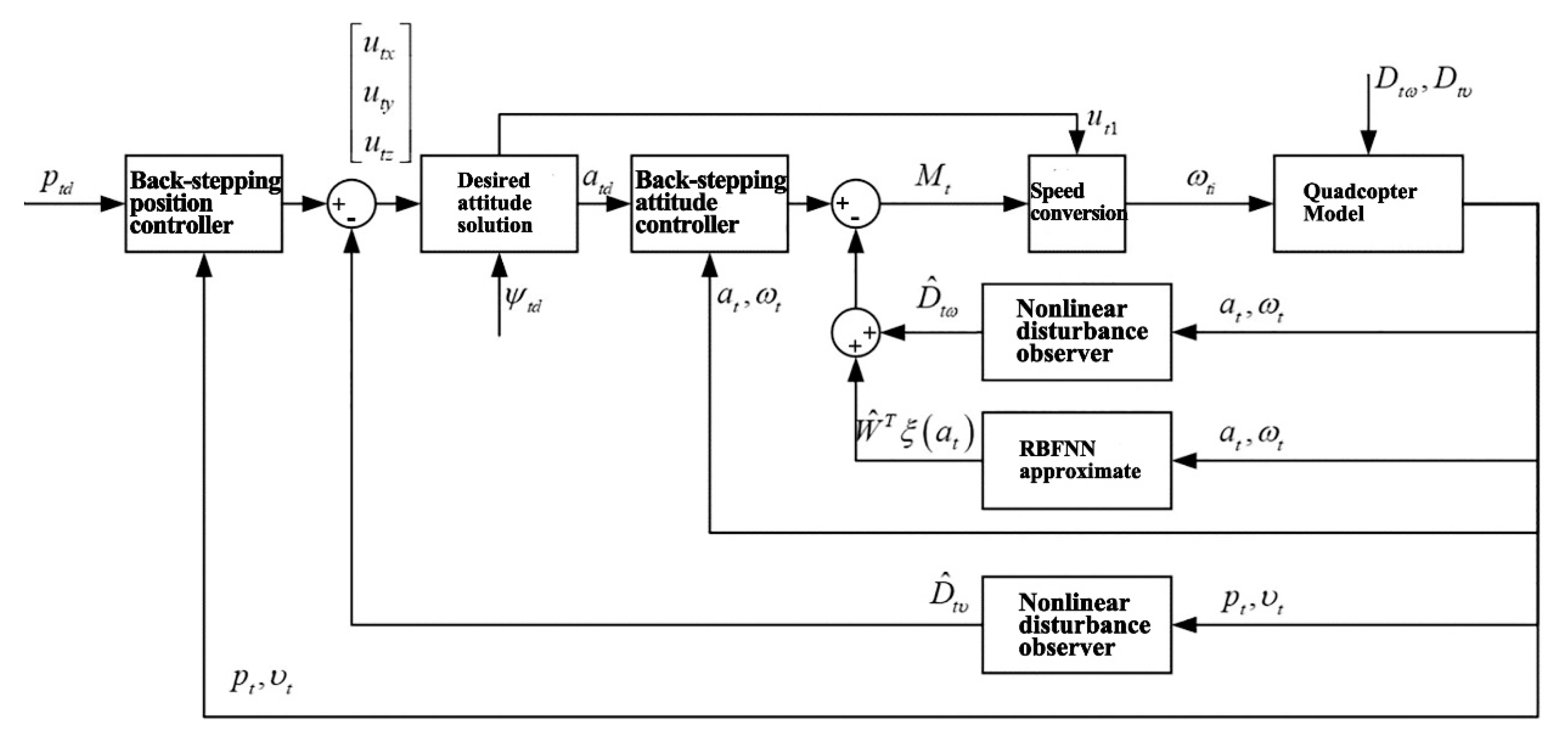
Sensors Free Full Text Design Of Airport Obstacle Free Zone Monitoring Uav System Based On Computer Vision Html

Analog Mems Microphone Block Diagram 16 Download Scientific Diagram

Block Diagram Of The Handheld Microphone Module Download Scientific Diagram

Block Diagram Of The Mems Microphone Array System Download Scientific Diagram

Block Diagram Of An Analog Front End Dedicated For Piezoelectric And Download Scientific Diagram

Analog Devices Cn0262 Block Diagram Mems Microphone Analog Devices Circuit Diagram

Akustica S Mems Microphones For Smartphones And Wearables Edn

Circuit Diagram Of Condenser Mircophone Coupler Circuit Diagram Circuit Circuit Design
Remotemix One Vortex Communications Ltd

System Block Diagram The Microphone Array Provides Audio Inputs To The Download Scientific Diagram

Block Diagram Of The Two Microphone Noise Reduction System With Nearby Download Scientific Diagram

Microphone Circuit Diagram Electrical Circuit Diagram Circuit Diagram Electronic Circuit Design

Block Diagrams For Different Types Of Mems Microphones Analog I 2 S Download Scientific Diagram